
Photon-grade
measurement systems.
Each Skovomax technology is engineered as a complete optical system — from the physics of photon generation, through propagation and target interaction, to detection, timing, and information reconstruction.
LiDAR is a
closed-loop light system.
Photon emission → interaction → return → detection → timing → reconstruction. From a pure photonics viewpoint, LiDAR is not a sensor — it is a laser-based measurement system that captures the geometry and structure of the physical world.
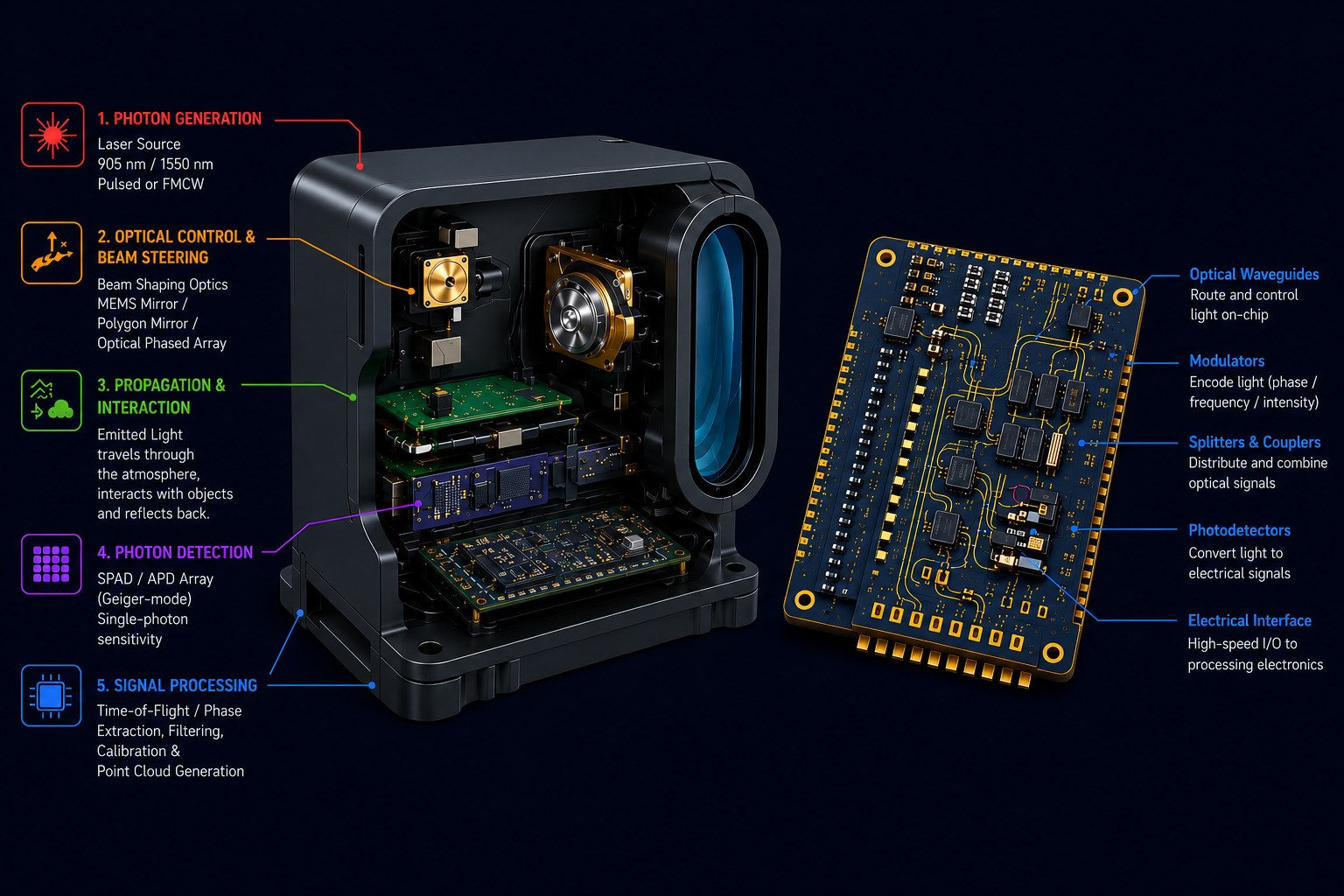
Light Generation
A laser source emits controlled photons.
Propagation
Light travels through atmosphere (scatter, attenuation).
Interaction
Reflection (primary), partial absorption, surface-dependent response.
Return Signal
Reflected photons return to the sensor.
Detection
Photodetector converts photons → electrical signal.
Interpretation
Time delay + intensity → distance + structure.
Closed-loop
optical architectures.
A photonic sensor is an engineered pipeline — laser source, beam shaping, target interaction, photodetection, and signal processing — treated as a single optical system. Range, velocity, and material signatures fall out of the physics.
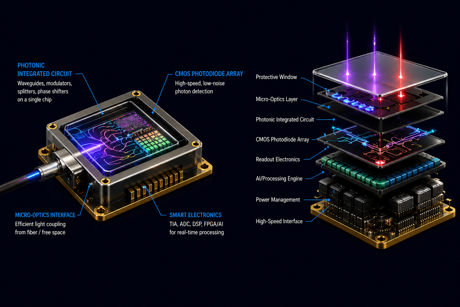
Laser Source
Coherent emission — fiber lasers, DFB diodes, narrow-linewidth sources for phase-stable measurement.
Beam Shaping
Collimators, MEMS / galvo scanners, diffractive optics that control divergence and spot geometry.
Target Interaction
Reflection, absorption, and scattering carry the information the measurement is trying to extract.
Photodetection
APDs, SPADs, and balanced photodiodes convert returning photons into electrical signal with timing fidelity.
Signal Processing
Time-of-flight, FMCW, or coherent phase pipelines reconstruct distance, velocity, and structure.
- Time-of-Flight — direct photon travel time → range.
- FMCW — frequency-modulated coherent detection → range + velocity.
- Phase-based — modulated intensity phase shift → short-range precision.
- Range / SNR — source power, detector sensitivity, aperture.
- Eye-safety — 1550 nm operating window.
- Coherence — narrow linewidth enables FMCW + interferometric sensing.
Doped optical fiber
as gain medium.
The gain medium is an optical fiber doped with rare-earth elements — Ytterbium (Yb³⁺), Erbium (Er³⁺), or Thulium (Tm³⁺). Instead of a bulk crystal, the fiber itself generates and amplifies light, delivering diffraction-limited beams with M² < 1.1 at kilowatt power.
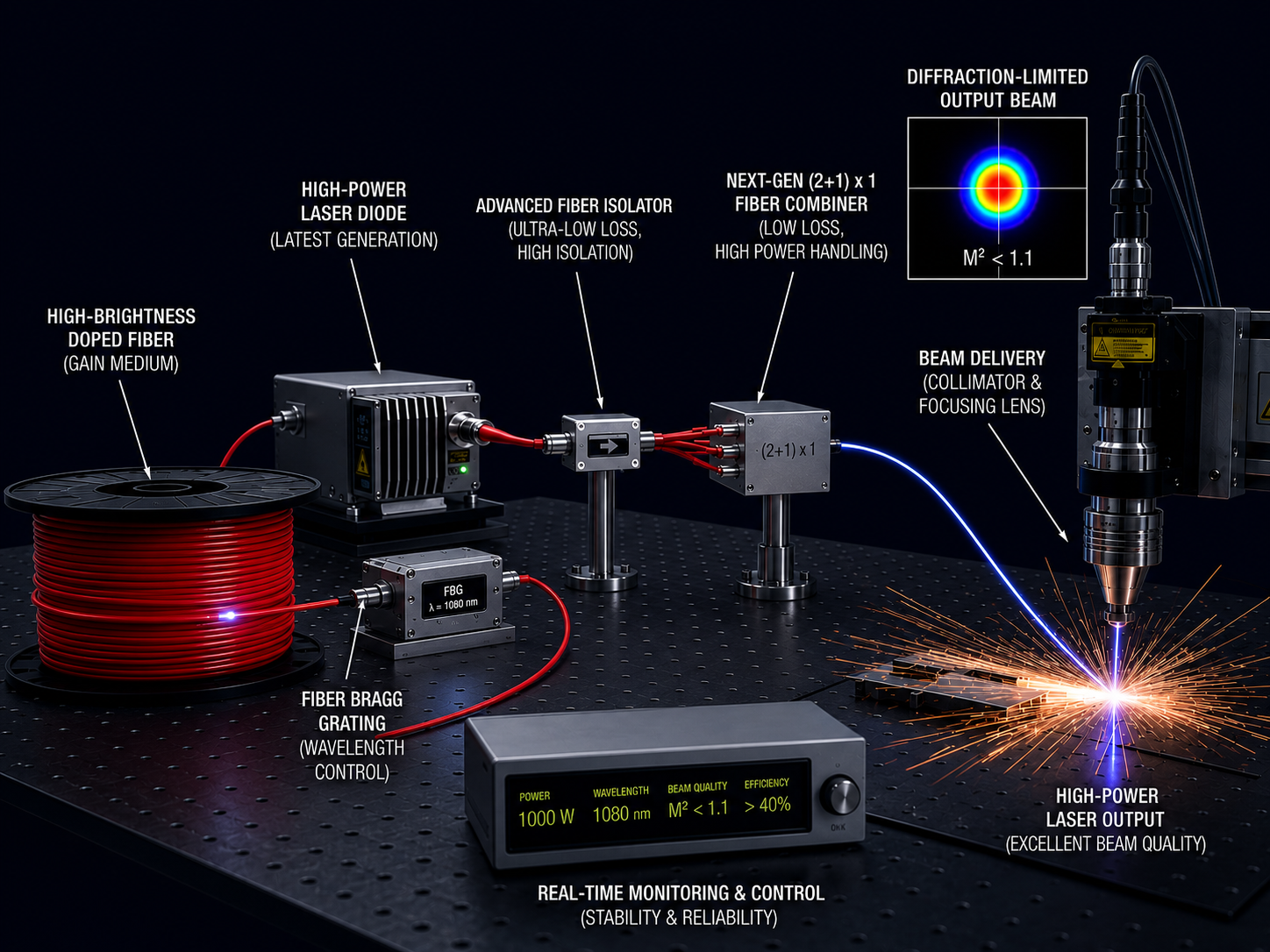
Pumping
External laser injects energy into doped fiber.
Excitation
Rare-earth ions absorb energy → excited state.
Stimulated Emission
Incoming photons trigger emission of identical photons.
Amplification
Light is amplified as it travels through fiber.
Resonance
Cavity builds coherent laser output.
- High Efficiency — excellent heat dissipation via fiber geometry.
- Beam Quality — highly coherent output.
- Compact & Robust — no complex bulk alignment.
- Scalable Power — low-power sensing to high-power industrial.
- LiDAR systems — stable laser source, eye-safe 1550 nm.
- Environmental monitoring — mid-IR sensing (Thulium).
- Coherent LiDAR (FMCW) — phase-accurate ranging.
- Optical communication — sensing networks, telemetry.
Pattern intelligence
from spatial data.
“Data are not just numbers, they are numbers with a context. In data analysis, context provides meaning.” — Cobb & Moore, 1997. Geospatial analytics adds timing and location to traditional data, revealing insights lost in spreadsheets.
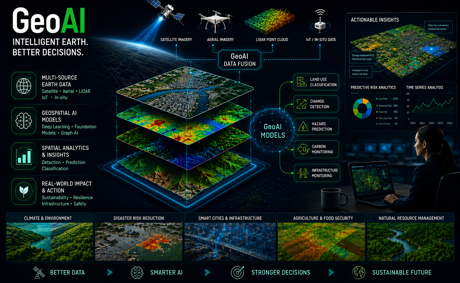
Feature extraction from imagery
CNNs + classical CV on hyperspectral, multispectral and SAR.
Classification from point clouds
Supervised and self-supervised segmentation of LiDAR scans.
Deep learning for geoscience
Spatial diffusion, gravity models, multi-criteria AHP/TOPSIS.